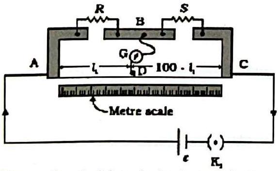
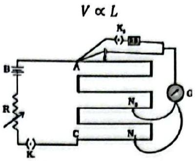
(a) Draw a circuit diagram of a metre bridge used to determine the unknown resistance R of a wire, and derive the expression for R in terms of the known resistance S. (b) What is meant by 'end error' in a metre bridge and how is it corrected? How is the balancing point affected if the positions of the battery and galvanometer are interchanged? \\ \textbf{OR} \\ (a) State the working principle of a potentiometer and, with a circuit diagram, explain how the internal resistance of a cell is determined. (b) How are the readings affected when (i) the internal resistance of the driver cell increases and (ii) the series resistor of the driver circuit is reduced?
Solution
(a) A metre bridge is a balanced Wheatstone bridge with the 1 m wire forming two arms. At the null point SR=100−ℓ1ℓ1, so R=S100−ℓ1ℓ1. (b) \textbf{End error}: the zero of the scale and the ends of the wire do not coincide, and the end strips/contacts add small resistances; this shifts the balance point. It is corrected by repeating with R and S interchanged and averaging, or by adding measured end corrections. Interchanging the cell and galvanometer does not disturb the balance condition SR=100−ℓ1ℓ1, so the balancing point is unchanged. \textbf{OR:} principle V∝ℓ. Balancing the cell's EMF (external key open) gives E∝ℓ1; closing a known R across it and balancing the terminal voltage gives V∝ℓ2, so r=R(ℓ2ℓ1−1). (i) A larger driver internal resistance reduces the wire current and gradient, so a given EMF balances at a greater length. (ii) Reducing the series resistor increases the current and gradient, so the balancing length decreases.