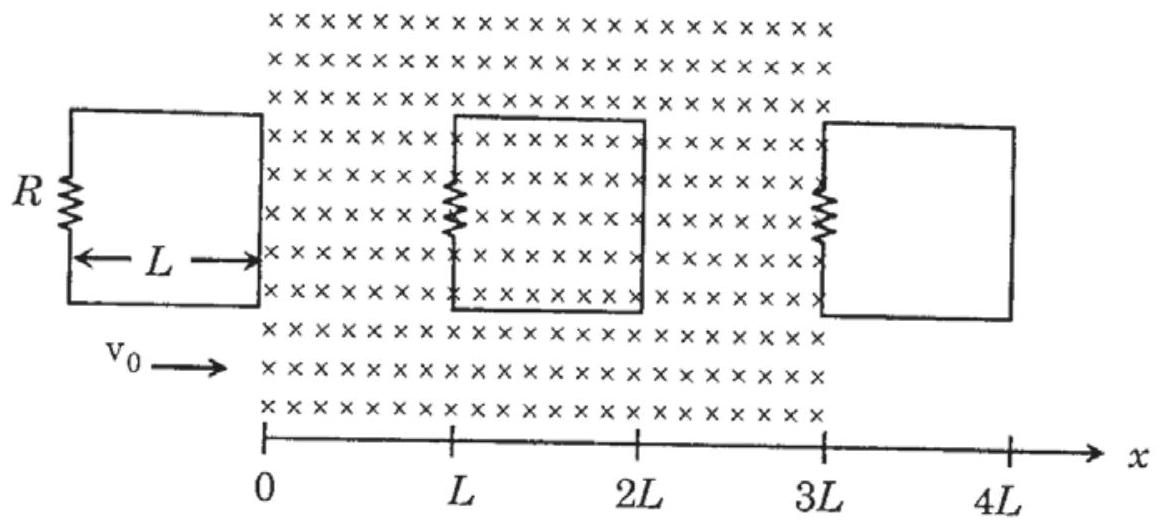
A rigid wire loop of square shape having side of length L and resistance R is moving along the x-axis with a constant velocity v0 in the plane of the paper. At t=0, the right edge of the loop enters a region of length 3L where there is a uniform magnetic field B0 into the plane of the paper, as shown in the figure. For sufficiently large v0, the loop eventually crosses the region. Let x be the location of the right edge of the loop. Let v(x),I(x) and F(x) represent the velocity of the loop, current in the loop, and force on the loop, respectively, as a function of x. Counter-clockwise current is taken as positive.
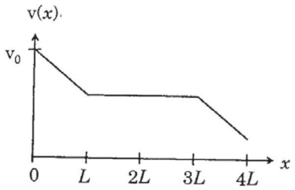
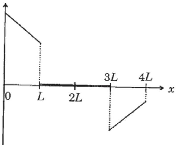
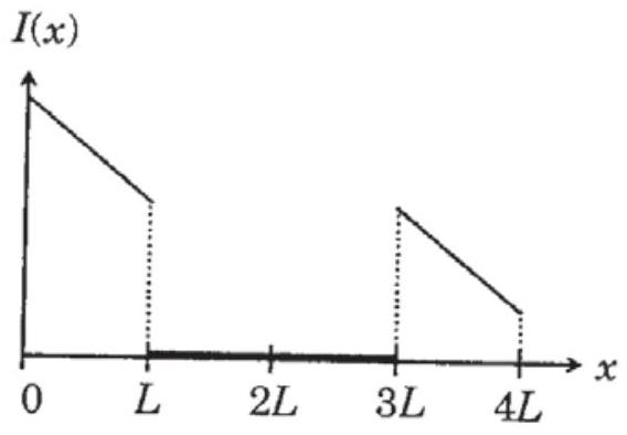
Which of the following schematic plot(s) is(are) correct? (Ignore gravity)
(A)(see structure)✓ Correct
(B)(see structure)✓ Correct
(C)(see structure)
(D)(see structure)
Answer: (A), (B)
Solution
Region 1 (0 < x < L): Right edge entering field.
Induced emf: ε=BLv, current i=RBLv (positive/counter-clockwise)
Force: F=BiL=RB2L2v (leftward, opposing motion)
Equation of motion: mdtdv=−RB2L2v
This gives v(x)=v0−mRB2L2x (linear decrease)
Region 2 (L < x < 3L): Entire loop in field, no flux change, i=0, F=0, v constant.
Region 3 (3L < x < 4L): Left edge leaving field.
Current reverses (clockwise/negative), force opposes motion again.
Plots (A) and (B) correctly show these features: the current is positive and linearly decreasing while the loop enters, zero while it is fully inside, and negative while it leaves, with the force a mirror of the current; the velocity falls linearly, stays constant, then falls linearly again.
JEE Advanced · 2016 · 22 May 2016 · Paper 2 · One or more correct options