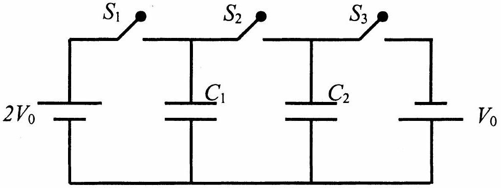
In the circuit shown in the figure, there are two parallel plate capacitors each of capacitance C. The switch S1 is pressed first to fully charge the capacitor C1 and then released. The switch S2 is then pressed to charge the capacitor C2. After some time, S2 is released and then S3 is pressed. After some time,
(A) the charge on the upper plate of C1 is 2CV0. (B) the charge on the upper plate of C1 is CV0. (C) the charge on the upper plate of C2 is 0. (D) the charge on the upper plate of C2 is −CV0.
(A)the charge on the upper plate of C1 is 2CV0.
(B)the charge on the upper plate of C1 is CV0.✓ Correct
(C)the charge on the upper plate of C2 is 0.
(D)the charge on the upper plate of C2 is −CV0.✓ Correct
Answer: (B), (D)
Solution
Step 1: When S1 is closed, C1 charges to 2V0, so charge on C1=2CV0.
Step 2: When S2 is pressed (S1 open), C1 and C2 share charge:
Vcommon=C+C2CV0=V0
Charge on C1=CV0 (upper plate positive)
Charge on C2=CV0 (upper plate positive)
Step 3: When S3 is pressed (S2 open), C2 is connected in reverse polarity. The charge on C2 remains CV0 but with upper plate negative.
Therefore:
Charge on upper plate of C1=CV0 ✓ (B is correct)
Charge on upper plate of C2=−CV0 ✓ (D is correct)
Hence the correct answers are (B) and (D).
JEE Advanced · 2013 · 02 Jun 2013 · Paper 1 · One or more correct options