CBSE Class 12 · 2009 · SemiconductorsShort Answer

WhatsApp Email
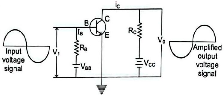
Give a circuit diagram of a common emitter amplifier using an n-p-n transistor. Draw the input and output waveforms of the signal. Write the expression for its voltage gain.

Solution

Circuit: an n-p-n transistor with the base-emitter junction forward biased by a base resistor and the collector-emitter output reverse biased through a collector load ; the ac signal is applied to the base and output taken at the collector.
When the signal increases the forward bias, rises and the collector voltage falls, so the output is out of phase with the input.
Voltage gain:
CBSE Class 12 Board · 2009 · Subjective

More board questions on Semiconductors

  1. A pure Si crystal having atoms is doped with 1 ppm concentration of antimony. If the concentration of holes in the doped crystal is found to be , the concentration (in ) of intrinsic charge carr …
    CBSE 2024View solution →
  2. (a) Explain the characteristics of a p-n junction diode that makes it suitable for its use as a rectifier.
    (b) With the help of a circuit diagram, explain the working of a full wave rectifier.
    CBSE 2024View solution →
  3. Explain the following, giving reasons.
    (a) A doped semiconductor is electrically neutral.
    (b) In a p-n junction under equilibrium, there is no net current.
    (c) In a diode, the reverse current is practically independent of the applied voltage.
    CBSE 2024View solution →
  4. In an extrinsic semiconductor, the number density of holes is . If the number density of intrinsic carriers is , the number density of electrons in it is
    CBSE 2023View solution →
  5. Pieces of copper and of silicon are initially at room temperature. Both are heated to temperature T. The conductivity of
    CBSE 2023View solution →
  6. The formation of depletion region in a p-n junction diode is due to
    CBSE 2023View solution →