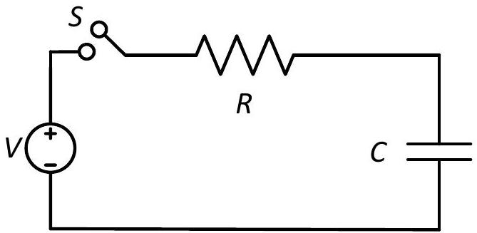
Consider a simple RC circuit as shown in Figure 1. Process 1: In the circuit the switch S is closed at t=0 and the capacitor is fully charged to voltage V0 (i.e., charging continues for time T≫RC). In the process some dissipation (ED) occurs across the resistance R. The amount of energy finally stored in the fully charged capacitor is EC.
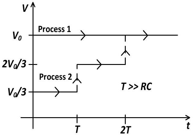
Process 2: In a different process the voltage is first set to 3V0 and maintained for a charging time T≫RC. Then the voltage is raised to 32V0 without discharging the capacitor and again maintained for a time T≫RC. The process is repeated one more time by raising the voltage to V0 and the capacitor is charged to the same final voltage V0 as in Process 1.
These two processes are depicted in Figure 2.
Consider a simple RC circuit as shown in Figure 1.
Process 1: In the circuit the switch S is closed at t=0 and the capacitor is fully charged to voltage V0 (i.e., charging continues for time T≫RC). In the process some dissipation (ED) occurs across the resistance R. The amount of energy finally stored in the fully charged capacitor is EC.
Process 2: In a different process the voltage is first set to 3V0 and maintained for a charging time T≫RC. Then the voltage is raised to 32V0 without discharging the capacitor and again maintained for a time T≫RC. The process is repeated one more time by raising the voltage to V0 and the capacitor is charged to the same final voltage V0 as in Process 1.
These two processes are depicted in Figure 2.
In Process 2, total energy dissipated across the resistance ED is:Figure 1Figure 2
(A)ED=21CV02
(B)ED=3(21CV02)
(C)ED=31(21CV02)✓ Correct
(D)ED=3CV02
Answer: (C)
Solution
When a capacitor is charged from Vi to Vf, heat dissipated is H=21C(Vf−Vi)2. Total heat in Process 2: ED=21C[(3V0)2+(3V0)2+(3V0)2]=21C⋅3⋅9V02=61CV02=31(21CV02).
JEE Advanced · 2017 · 21 May 2017 · Paper 2 · Single correct option