JEE Advanced · 2009 · 12 Apr 2009 · Paper 1 · Current Electricity

WhatsApp Email
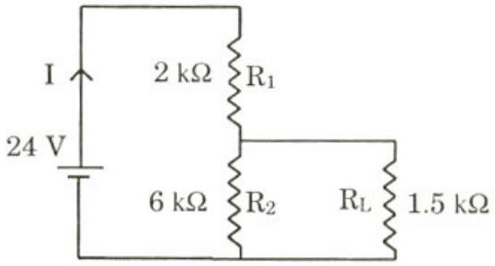
For the circuit shown in the figure
  1. (A)the current through the battery is 7.5 mA✓ Correct
  2. (B)the potential difference across is 18 V
  3. (C)ratio of powers dissipated in and is 3
  4. (D)if and are interchanged, magnitude of the power dissipated in will decrease by a factor of 9✓ Correct

Answer: (A), (D)

Solution

Applying Kirchhoff's laws to the circuit with kΩ, kΩ, kΩ, and battery voltage 24 V. Let be the current through the battery and be the current through . From the loop equations: and . Solving gives mA and mA. When and are interchanged, solving the new equations gives mA and mA. The power in is proportional to , so . Therefore, options (A) and (D) are correct.

JEE Advanced · 2009 · 12 Apr 2009 · Paper 1 · One or more correct options
More JEE Advanced questions on Current Electricity

  1. A metal wire of cross-sectional area and length 100 m is connected across a battery of e.m.f. 2 V and internal resistance . The density, atomic mass and electrical conductivity of the metal are …
    JEE Advanced 2026View solution →
  2. As shown in the figure, the resistance of a galvanometer can be found by the half-deflection method. Here the resistance is adjusted such that when the key is closed the deflection in the galvanometer becomes half of the value as compared to when is op …
    JEE Advanced 2026View solution →
  3. In a circuit shown in the figure, the capacitor is initially uncharged and the key is open. In this condition, a current of 1 A flows through the resistor. The key is closed at time . Which of the following statement(s) is(are) correct?
    [Given: …
    JEE Advanced 2023View solution →
  4. The figure shows a circuit having eight resistances of each, labelled to , and two ideal batteries with voltages and .

    Which of the following statement(s) is(are) correct?
    JEE Advanced 2022View solution →
  5. Two resistances and are connected to a wire of uniform resistivity, as shown in the figure. The radius of the wire varies linearly along its axis from at to at . A galvanometer (G) connected to the center …
    JEE Advanced 2022View solution →
  6. In Circuit-1 and Circuit-2 shown in the figures, and . and are the power dissipations in Circuit-1 and Circuit-2 when the switches and are in open conditions, respectively.
    and …
    JEE Advanced 2022View solution →