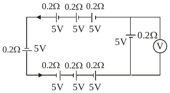
The reading in the ideal voltmeter (V) shown in the given circuit diagram is:
(A)5 V
(B)10 V
(C)0 V✓ Correct
(D)3 V
Answer: (C)
Solution
The network is symmetric: two branches of identical 5 V cells (internal resistance 0.2 Ω) feed into a common 0.2 Ω resistor leading to the voltmeter node. By symmetry, the circuit reduces to a single loop of emf 5 V and total resistance 0.2 Ω.
i=rE=0.25=25A
The terminal potential difference across the branch carrying the voltmeter is
V=E−ir=5−0.2×25=0V
The ideal voltmeter therefore reads 0 V.
JEE Main · 2024 · 01 Feb 2024 · Shift 1 · Single correct option