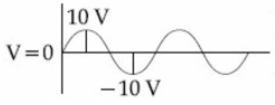
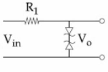
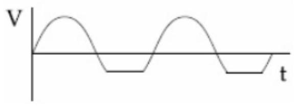
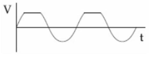
Take the breakdown voltage of the zener diode used in the given circuit as 6 V . For the input voltage shown in figure below, the time variation of the output voltage is: (Graphs drawn are schematic and not to scale)
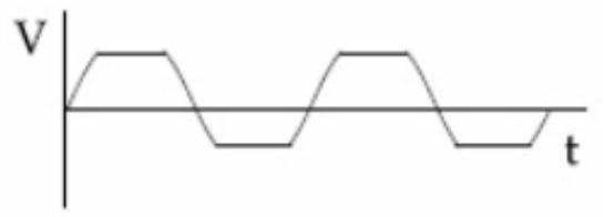
(A)(see structure)✓ Correct
(B)(see structure)
(C)(see structure)
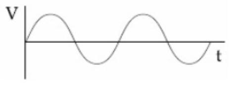
(D)(see structure)
Answer: (A)
Solution
A Zener diode held in reverse bias clamps the voltage across it once the input reaches its breakdown value, here 6 V. As long as the input stays below 6 V the diode does not break down and the output simply follows the input, but the moment the input tries to exceed 6 V the Zener conducts and holds the output fixed at 6 V, flattening the tops of the positive half-cycles. During the negative half-cycle the Zener is forward biased and behaves like an ordinary conducting diode with only a small drop of about 0.7 V, so the output stays close to zero. The waveform whose positive peaks are clipped at +6 V while the negative portions sit near zero is the one that matches this behaviour.
JEE Main · 2020 · 04 Sep 2020 · Shift 1 · Single correct option