JEE Main · 2009 · 12 Apr 2009 · Offline · Semiconductors

WhatsApp Email
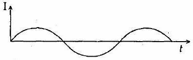
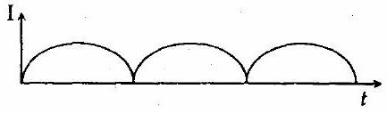
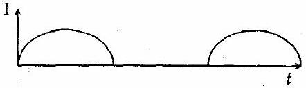
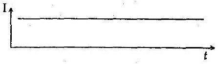
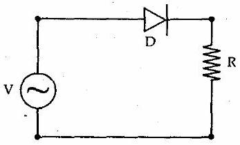
A p-n junction (D) shown in the figure can act as a rectifier. An alternating current source () is connected in the circuit.
  1. (A)(see structure)
  2. (B)(see structure)
  3. (C)(see structure)
    ✓ Correct
  4. (D)(see structure)

Answer: (C)

Solution

The single diode in series with the load makes this a half-wave rectifier. During the half of the input cycle that forward-biases the diode it conducts and the load carries current, while during the opposite half the diode is reverse-biased and blocks the current completely. The load therefore sees only the half-cycles of one polarity, so the output is the waveform in which alternate half-cycles are chopped off and only one set of humps survives.

JEE Main · 2009 · 12 Apr 2009 · Offline · Single correct option
More JEE Main questions on Semiconductors

  1. Find the correct combination of A, B, C and D inputs which can cause the LED to glow.
    JEE Main 2026View solution →
  2. For the given logic gate circuit, which of the following is the correct truth table?
    JEE Main 2026View solution →
  3. A voltage regulating circuit consisting of Zener diode, having break-down voltage of 10 V and maximum power dissipation of 0.4 W, is operated at 15 V. The approximate value of protective resistance in this circuit is ______ .
    JEE Main 2026View solution →
  4. Identify the correct truth table of the given logical circuit.
    JEE Main 2026View solution →
  5. Two p-n junction diodes and are connected as shown in figure. A and B are input signals and C is the output. The given circuit will function as a ______.
    JEE Main 2026View solution →
  6. The given circuit works as :
    JEE Main 2026View solution →