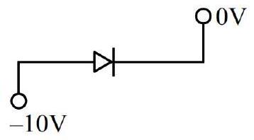
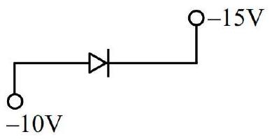
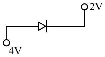
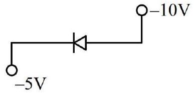
Which of the following circuits represents a forward biased diode?
Choose the correct answer from the options given below:(A)(B)(C)(D)(E)
(A)(B), (D) and (E) only
(B)(A) and (D) only
(C)(B), (C) and (E) only✓ Correct
(D)(C) and (E) only
Answer: (C)
Solution
A junction diode conducts (is forward biased) only when its p-side (the anode, marked by the arrowhead of the diode symbol) sits at a higher potential than its n-side (the cathode, the flat bar).
Reading each circuit's anode and cathode potentials from the arrow direction shown:
(A): anode at −10V, cathode at 0V — anode potential is lower than the cathode's, so the diode is reverse biased.
(B): anode at −10V, cathode at −15V — anode potential exceeds the cathode's, so the diode is forward biased.
(C): anode at 4V, cathode at 2V — anode potential exceeds the cathode's, so the diode is forward biased.
(D): anode at −10V, cathode at −5V — anode potential is lower than the cathode's, so the diode is reverse biased.
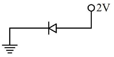
(E): anode at 2V, cathode at 0V (ground) — anode potential exceeds the cathode's, so the diode is forward biased.
Only diodes (B), (C) and (E) are forward biased.
JEE Main · 2025 · 22 Jan 2025 · Shift 1 · Single correct option