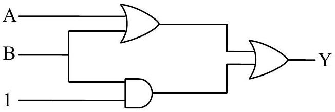
The output (Y) of logic circuit given below is 0 only when :
(A)A=1,B=0
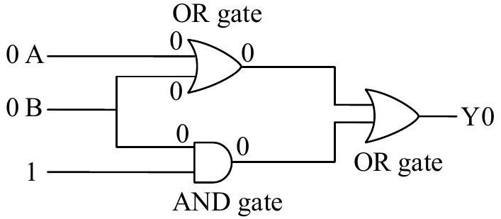
(B)A=0,B=0✓ Correct
(C)A=1,B=1
(D)A=0,B=1
Answer: (B)
Solution
From the logic circuit diagram, we can trace the logic operations:
The circuit consists of:
Two NOT gates on inputs A and B, producing A and B
An OR gate combining A and B
The output is:
Y=A+B
This is equivalent to A⋅B by De Morgan's law (NAND operation).
Truth table:
A
B
A
B
Y = A+B
0
0
1
1
1
0
1
1
0
1
1
0
0
1
1
1
1
0
0
0
Wait, let me reconsider. Looking at the circuit more carefully:
If the output is an AND gate of A and B:
Y=A⋅B
This gives Y = 0 except when both A = 0 and B = 0.
Actually, for Y to be 0, we need A⋅B=0, which happens when at least one of A or B is 0, i.e., when A = 1 or B = 1.
For Y = 1, both A=1 and B=1, meaning A = 0 and B = 0.
But the question asks when Y = 0. From the given answer (2), Y = 0 only when A = 0, B = 0, which suggests the circuit is NOR gate: Y=A+B.
For NOR gate, Y = 0 when A = 1 or B = 1 (or both), and Y = 1 only when A = 0 and B = 0.
Given the answer is (2) A = 0, B = 0, the circuit must produce Y = 0 for this input, suggesting it's an OR gate: Y = A + B, which gives 0 only when both inputs are 0.
Answer: (2)
JEE Main · 2024 · 05 Apr 2024 · Shift 2 · Single correct option